Programming Steps For Initially Setting Up A New Model
11/2/25
Document Title: Programming Steps for initially setting up a new model using a Spektrum Transmitter/Receiver. We are using an NX8+ transmitter and a AR637T receiver for this instruction manual. These instructions may apply to other combinations of transmitters and receivers, but it is up to the user to verify correctness if other combinations of Spektrum transmitters and receivers are being programmed by these procedures.
Author: Stephen H. Nussbaum: Member of Chollas RC Flyers Club, San Diego, CA.
Purpose: Provide a step-by-step procedure to follow when you have a new model to program from scratch.
Approach: We will use a sample model with typical characteristics that are found in a basic intermediate level plane. It is important to follow the sequence of these procedures because some steps cannot be properly completed ahead of others. The programming or setup is presented in two phases; Phase 1 provides the initial steps we need to take exclusively with the transmitter to start creating a new model file and before applying power and binding the transmitter to the model. Phase 2 provides the steps we need to take to complete the programming of the new model with the model powered up and bounded to the transmitter.
Sample Model: Our fictitious example model is very similar to an Eflite P-47 Thunderbolt PNP version. It requires the user to provide a receiver. We will use the Spektrum AR637T receiver. This receiver has 6 channels for servos and additional auxiliary channels which we will use for features such as flight mode selection, braking etc. This receiver also has telemetry capability as indicated by the “T” in the model number. We will use this capability to send electronic speed controller (ESC) and airspeed data down to the transmitter.
Our example model has the following features:
A programmable Avian Smart ESC, we will program this ESC for operational brakes (reverse thrust).
A user installed AR637T receiver. We will use its telemetry feature in this setup.
Wing design that uses one Aileron channel (CH 2) to drive two aileron servos by using a “Y” cable adapter.
As part of the wing design, we will have operational Flaps (CH6) using a “Y” adapter to allow two flap servos to be driven from one servo channel. We will assign switch D (3-position) for the flaps operation. Switch D will allow us to select: 1. No flaps; 2. Half flaps; and 3. Full flaps.
Operational Electric Retract landing gear, using a “Y” adapter to drive both gear servos from one output (CH5). We will assign switch A (2-position) to channel 5 on the transmitter for selecting gear-up or gear-down.
The complete servo assignments are as follows: (very typical)
CH1-Throttle
CH2-Ailerons
CH3-Elevator
CH4-Rudder
CH5-Landing Gear
CH6-Flaps
CH7-AUX 7 Flight Mode select (Normal, AS3X and SAFE)
CH8-AUX 8 Reverse thrust braking
We will program this system for three user selectable Flight Modes. We will assign switch B (3-position) for this use. We will use one of the auxiliary channels, CH7 (AUX7) to send the Flight Mode switch selection to the receiver. The three positions will be, Normal Mode (no gyro), AS3X Mode (stability mode) and SAFE Mode (auto-leveling). If your program is updated with AS3X+, there is no change to this procedure.
We will program this system for user selectable braking. This is done through the reverse thrust capability of the ESC. Reverse thrust means reversing the motor rotation. We will assign to switch C (3-position) for this use. We will use another available auxiliary channel, CH8(AUX8) to send the braking select switch state to the receiver. Although we do not need a 3-position switch for this function since the brakes are either On or Off, I chose this switch because it’s easy and fast to locate it by feel.
1.0 Phase 1. Setting up the Transmitter for a new model.
The first phase of procedures is done exclusively with the transmitter. The model remains turned off during this phase.
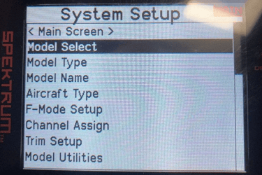
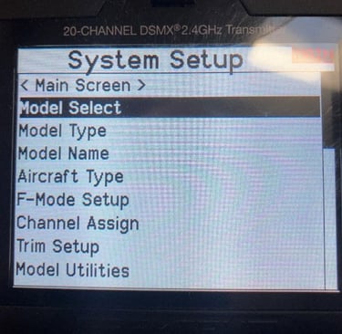
a. Turn on the NX8+ transmitter. Whenthe main page is displayed press the scroll wheel and you should see the Function List screen. Scroll down to the option System Setup. Figure 1. Function List shows the System Setup option is highlighted. Now click it.
b. After clicking “yes” on the orange caution screen you will see the System Setup menu. We will be going through this menu list in sequence.
c. From the System Setup list scroll to the Model Select option and click it. Figure 2.0 Model Select shows this option.
d. Then from the Model Select screen scroll down until you find the <Add New Model> option as shown in Figure 3.0 Model Select – Add New Model and click it.
e. You should now be seeing a screen titled Create New Model. The airplane graphic should be highlighted in the window. If it’s not a plane then click it and scroll until the plane is in the window and click it again to lock it in. Then scroll until the word “CREATE” is highlighted and click that. It will take 3-4 seconds after clicking CREATE to complete this step. After this time delay it will bring you back to System Setup. This step was critical. If you do not click on the word CREATE the system will not add a new model to the list and you could end up overwriting the data for another model that has already been programmed. Refer to Figure 4.0 for this step.
Figure 1.0 Function List
Figure 2.0 System Setup Screen-Model Select option
Figure 3.0 Model Select- Add New Model
Figure 4.0 Creating a new model file
f. Scroll down past Model Type because it already knows you’re programming an airplane and select Model Name, then click it. In the Model Name editor screen use the scroll wheel and scroll button to enter the model’s unique name. I will use the Acro_1 for this procedural example. Once you have typed that name in, click the back button until you get back to the System Setup screen. You can see in Figure 5.0 that I have entered Acro_1 for the name of our example.
Figure 5.0 Model Name editor
g. Scroll down to the next option, Aircraft Type and click it. This should bring you to the Aircraft Type screen. For this example, we have a normal aileron configuration, one on each wing. But since both aileron servos are operating from same, channel (CH2), using a “Y” cable adapter, you’ll need to select the option that says “1 aileron 1 flap”. The flaps use 2 servos as well and are driven from one channel (CH6). The number “1” refers to the number of channels you need use to control each pair of these surfaces. 1 Ail 1 Flap. Figure 6.0 Wing Type , shows the Aircraft Type screen and the option we want to use. Once the type 1 Ail 1 Flap is highlighted, click on the BACK button until you get back to the System Setup screen.
Figure 6.0 Aircraft Type selection
h. On the System Setup page scroll down to the next option after Aircraft Type, F-Mode Setup and click it. You will see on the Flight Mode Setup screen that there are three switches to choose from. We just need to assign Switch 1: to a switch we want to use for mode selections. I use switch B. Highlight this switch selection which should be showing Inhibit and click it. Use the scroll the wheel until Switch B shows in the highlighted area. This is a 3-position switch located in the upper left corner of the transmitter. You can use other switches; I typically use this switch because it’s easy to find without looking for it. It gives me 3 flight mode selections that we will define as; Normal, AS3X and SAFE modes. This is an arbitrary arraignment; you can assign any flight mode to any position of this switch. I just use this pattern because it makes sense to me. There is also a benefit that it is close to the throttle/rudder control stick. You can operate the switch and see the Mode: change with the switch selection. Right now, it just shows Flight Mode 1, 2, and 3. Later on when we get into Forward Programming, we will rename these modes to Normal, AS3X and SAFE respectively. And we will assign what each of these mode selections will do. We will also have the mode voiced once when you move the switch to a different position. This way you do not have to look at the screen to see what mode you’re in while you’re controlling your plane. But for now, just select switch B and go back to the System Setup screen. Figure 7.0 shows the Flight Mode Setup screen.
Figure 7.0 Flight Mode Switch Assignment
i. Scroll down another step to the Channel Assign option and click it. On the Channel assignment screen, it shows all the channels and what is assigned to them.
a. Ch 1-4: The first 4 channels are already factory assigned to; throttle, ailerons, elevators and rudder.
b. Channel 5 (Gear) has Switch A as the input source which we can change to another switch if we want to, right here on this screen. Just edit the switch letter A to another switch using its letter designation that you want to use. Later, when we test the gear, we will be able to program which switch position we want for gear UP and gear DOWN, in accordance to your preference. For now, we will just assign the Switch A for this function. We will assign the gear operation later.
c. Channel 6 (Flaps) later we will assign Switch D assigned for flaps. It could be done here as well. User choice. I wait because you’ll need to adjust the flap range and direction, so I do it all in a single effort.
d. Channel 7 (Flight Modes) AUX7 shows Switch B will be used for flight mode selection. We previously assigned Switch B for this on the flight mode page. Nothing more needs to be done here.
e. Channel 8 (Reverse Thrust) AUX 8. This channel has the Rknb as the default assignment by the factory as its input source. We want to change that to Switch C, so scroll down to the Rknb and highlight it and click it. Scroll until Switch C is in this position and click on BACK to save this change and return to the System Setup screen. Switch C is a 3-position. We only need a 2-position switch, but I like the location of Switch C for this function. We will program it so FWD is position “0” and :1: and Reverse will be activated in position “3”.
Figure 8.0 Channel Assignments
j. That’s it for Phase 1. What we’ve done here will help get us set up for programming with the receiver powered up. Next, we will go through Phase 2. Which is setting up the receiver and all of the various modes we are going to use with the transmitter linked up to the receiver. We will finish by setting up the Flight Modes and we will also set up the Telemetry system in Phase 2.
2.0 Phase 2. Setting up the receiver.
Safety Requirement: Please have the propeller removed prior to proceeding with Phase 2. These instructions will advise when it is time to put the propeller back on.
Overview of Phase 2. sequence:
In Phase 2. we will set up the receiver using the following sequence:
We will bind the receiver to the transmitter for the new model. It is important that phase 1 has been completed and the new model that we named, Acro_1, is being shown on the first screen.
Setting up Throttle Cut
Setting up the flight timer.
Initial servo checks.
Initial servo rates setting.
Checking the landing gear operation
Programming the flap operation.
Setting up the telemetry screen
Programming the ESC for reverse thrust braking
Return to the servo rates and trim for maiden flight preparation.
Programming the Flight Mode switch B for position names and audible call outs.
Programming for user selectable AS3X and SAFE operation using forward programming
a. This will include updating (relearning servos) the system with the latest servo information and calibrating the gyros.
b. Testing the safe mode
Install the propeller and test for proper rotation for forward and reverse thrust.
Final notes.
2.1 Binding
We need to bind the model’s receiver and transmitter together before we can do any further programming. But before we do that, turn on the transmitter and select Acro_1 using the Model Select function. The new model, Acro_1, must be showing up on the main screen before we can proceed with the binding process. There are several ways of going through the binding process; the method I use is as follows:
Plug the battery in and immediately press the bind button on the receiver. The amber led inside the receiver should start blinking rapidly. If you are using a secondary receiver (which I highly recommend) check for a rapidly blinking amber led it as well.
Then navigate to the Function List on the transmitter and scroll down to the Bind option and click it. On the BIND screen highlight BIND and click it. Wait for a few seconds and the receivers led should stop blinking and be turned on in a steady state. This indicates the binding process was successful. You are ready to move on. Figure 9.0 shows the screen for binding.
Figure 9.0 Binding Screen
2.2 Throttle Cut
This is a high priority safety feature obviously, so I prefer to set it up right after binding. On the main screen press the scroll roller to get to the Function List. Navigate down to the Throttle Cut option and click it. Figure 10.0 shows the Throttle Cut screen. I’ve been using Switch G, a 3-position switch, because Switch H (2-position) on my transmitter has malfunctioned. You will notice that the Position value is -100%. If you make this value less, say -80% the prop will start to rotate but limited to a low rpm range. So, keep this value at -100%. The switch position that enables the throttle, is position 0 (white background), positions 1 and 2 (black backgrounds) will keep the throttle disabled, i.e. throttle cut. Switch H, position 0 is physically in the full forward position and I like to think that to go forward, you move throttle cut switch forward followed by moving the throttle stick forward for increasing rpm. They are both “push” actions. You can change this style of which switch position enables and disables the throttle. To do that you need to go into the Digital Switch Setup screen. There you can reassign the values for each position and customize what affect each of the switch positions have on the throttle. But my logic says if I want to go forward to push the controls forward. That’s it for throttle cut. As a secondary safety step, you might consider programming an audio event (e.g., throttle on and throttle off) in the sound utilities menu (See section 2.11).
Figure 10.0 Throttle Cut
2.3 Flight Timer
The Flight Timer is a useful indicator that you can use to set an alarm to let you know how long you’ve been flying. The timer is typically set to warn you that your battery has discharged to a low state and it’s time to consider landing. You’ll want to test the timer’s duration so that when it times out you will still have sufficient battery power left for a few “go-arounds” before you are at a dangerously low battery level and risk facing a dead-stick landing. Navigate to the Function List, find the Timer option and click it. You will be taken to the timer screen where you can set timer parameters. I usually set my Count Down timer for 5 minutes. Additionally, it will only count down as long as the throttle exceeds 25%. Figure 11.0 shows the timer’s programming screen. I like to have from 20-50% of battery charge left when the timer times out. If it’s less than 20% I will reduce the timer’s duration until I have at least 20% left at the timeout.
Figure 11.0 Flight Timer
2.4 Initial Servo direction checks.
Operate each channel and verify the correct control surfaces are moving in the right direction for the given stick inputs. Check that the trim values on the main screen are all set for neutral. If a control surface is operating in reverse, navigate to the main Servo Setup screen and then to the REVERSE sub-screen and make the changes needed to make the surface(s) operate in the correct direction. Figure 12 shows the Servo Setup Reverse sub-screen. Verify this for all three axis; aileron, elevator, and rudder. We don’t want to do any trimming at this point because later on we will need to use the throttle/rudder control stick for programming the ESC and we will need full range of +,-100% from this control stick. We will go through trimming for flight after we finish programming the ESC for reverse thrust.
Warning: Reversing the throttle position will result in the motor going to full rpm when you plug the battery in. Please have the propeller removed from the motor until advised to install it in this procedure.
Figure 12.0 Servo Reverse Screen
2.5 Initial Servo Rate setup
In this section we need to make sure both the aileron and elevator servos reach +,-100% limits because we will need this range for programming the ESC later. When the ESC programming is complete, we will come back to the servo rate screen and put in values we will use for the maiden flight. After the maiden flight you may want to come back to the servo rate screen and re-adjust the rates to suit your needs. The rudder servo rate can be left at default which should be 100%. I’ve never had to reduce the rudder rate for improved performance.
Usually, the default servos rates will already be set for +-,100 %. To check this, scroll one page to the right of the main page to get to the Monitor screen. Once you’re on this screen, swing the aileron/elevator control stick to their maximum positions and note the values on the screen. If you don’t reach +, - 100 %, for both ailerons and elevators channels, look at what parameter is limiting this value. Normally, for a new model the trim settings should be zero and the rates should be 100%. If for any reason any of these trims and rates are not at their default values, we need to reset them back to their initial values of 0 trim and 100% rates. Figure 13.0 shows the Monitor screen with the aileron and elevator control stick at one end of their maximum positions reaching -100% for full left bank and full up. We also need to be able to have 100% movement when the control sticks are full right bank and full up. This is all done in order to program the ESC for reverse thrust braking.
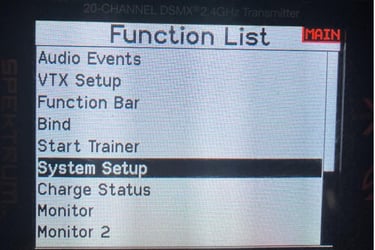
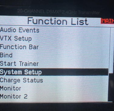
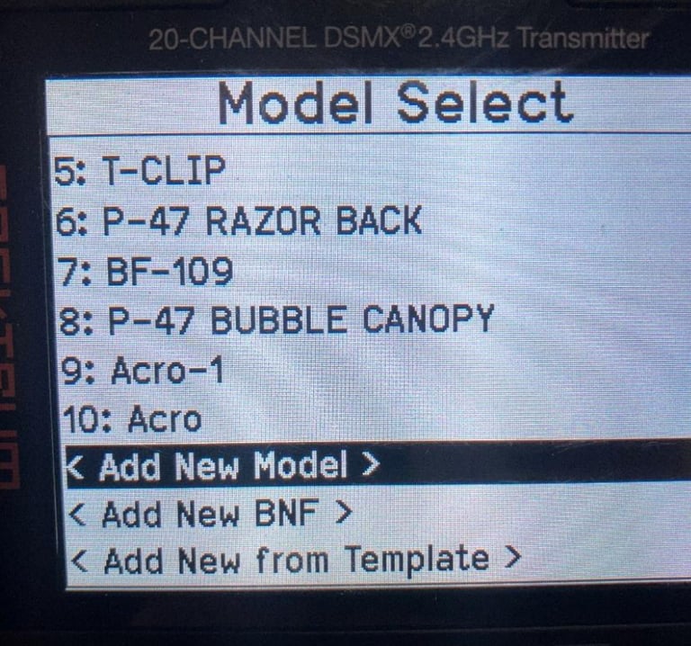
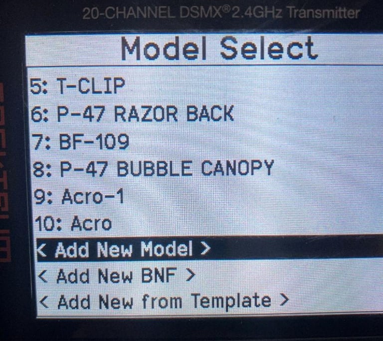
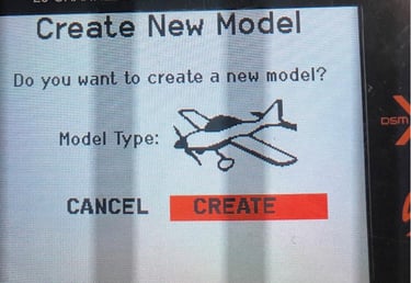
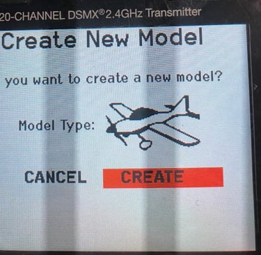
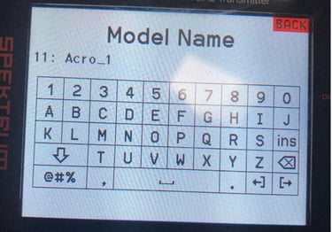
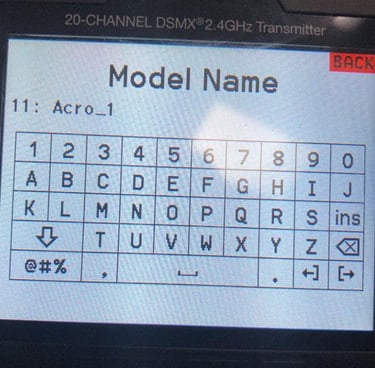
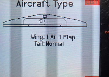
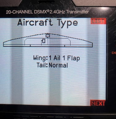
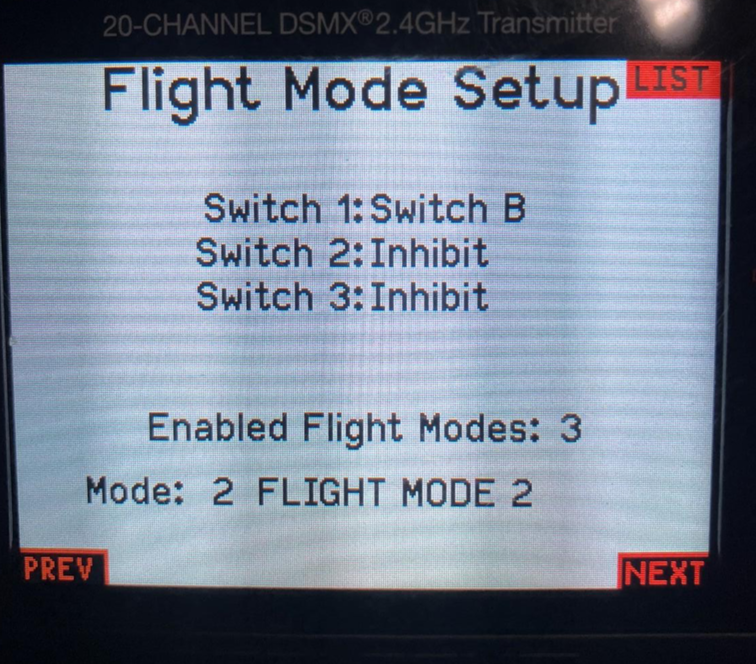
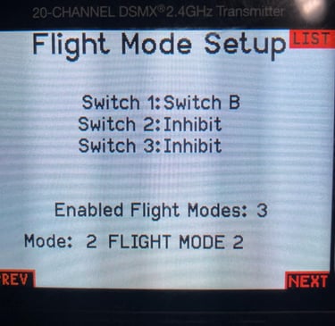
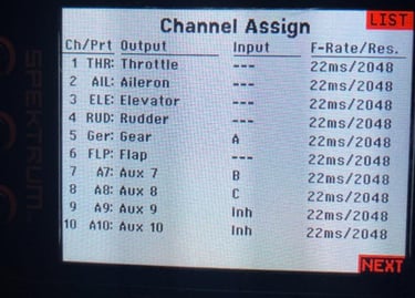
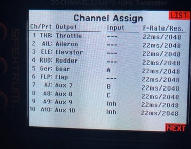
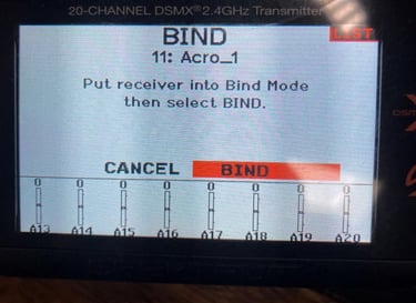
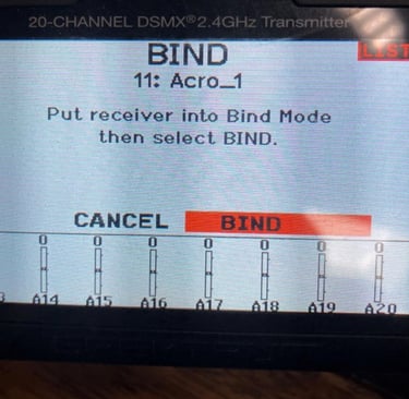
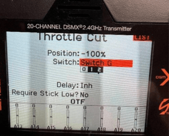
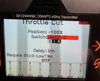
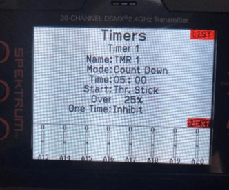
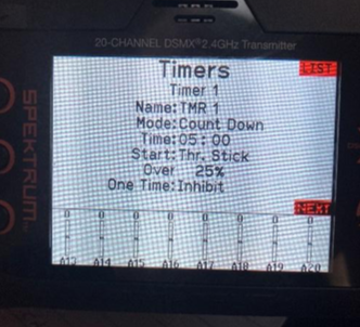
Figure 13.0.0 Monitor Screen
2.6 Checking the landing gear operation.
With the landing gear path free and clear to swing, use Switch A to raise and lower the gear. If the switch is working in reverse, navigate to the Digital Switch Setup screen and change the Switch A position values. If position 0 shows it is -100% and position 1 value is 100%, reverse those values and check the gear again. I prefer the full forward position on the switch for gear down, and back for gear up. You have the option to choose which way you want the gear to behave by adjusting the switch position values. You can also modify these position values to make small end point changes if the gear is not reaching its full travel limit. If Switch A does not have any effect on the gear, navigate to the Channel Assignment screen and verify that Switch A is assigned to servo channel 5. Back on Figure 8.0 it shows the Channel Assignment screen with Switch A assigned to the landing gear operation.
2.7 Programming the flap operation.
Navigate to the Function List and scroll down until you reach the option, Flap System, and click it. This will take you to the Flap System screen where you will see a Switch field which allows you to specify the switch you want to use to operate the flaps. I normally use Switch D for this function. Use the scroll wheel to put Switch D in the highlighted field and click it. Switch D is a 3-position switch, and each position is labeled Pos 0:, Pos 1:, Pos 2: . Figure 14.0 shows the Flap System screen. You will see two columns one labeled Flap, the other Elev. The Elev field allows you to mix in some elevator movement when the flap Switch D is used to raise or lower flaps. You will need to do some flight testing to see if you want to mix in some Elev to compensate for the extra lift you get with the flaps deployed. When you drop the flaps, the plane (real ones too) tends to move upward due to the extra lift created by lowering the flaps. In a real plane you would immediately re-trim the pitch to keep the plane on a descent.
However, re-trimming your RC takes time. Instead, you can automatically mix in some down
elevator to reduce the need to re-trim on final approach. I haven’t found that I really need to
mix in any trim. Just by reducing power, the plane will drop its nose anyway. Properly setting up
each control surfaces and establishing the correct center of gravity (CG) can greatly reduce the
need for excessive trim adjustments with your aircraft.
Figure 14.0 Flap System screen
Back to the Flap System screen. Initially the position values are default to “0%”. The upper
most position for Switch D is “Pos 0”. This is my full up selection. Put the switch in its full up
position, the screen should put a box around the “POS 0:” label and verify that your flaps are in
their full up position. Due to the mechanical orientation of the servo, you may see your flaps are
down instead of up. To change this, scroll to highlight the Pos 0 value in the flap column and
click it. Then scroll the number up or down while you watch the flaps respond. Scroll the value
until the flaps are in their full up position. Then position the switch in the middle position “Pos
1:” and scroll to the flap parameter next to it and click it. While observing the flap movement,
scroll the wheel until the flaps move to the middle or partially deployed position, referred to a half flaps. You can use this for take-offs or initially entering the landing pattern. You can change
this value later after you gain some experience using it. Then position the switch to the full
down position, “Pos 2”. Scroll to the flap value for Pos 2 and click it. Scroll until the flaps come
down to as far as they can go, i.e. full flaps.
The last thing to do here is to establish how fast the flaps deploy. This is accomplished with
the Speed: field. I usually use a 3 second transit time. Scroll to highlight this field and scroll until
3.0 seconds is showing and click it. Now when you change the flap position you will see it
operates at a much slower speed and this keeps the plane from shifting up or down quickly
when you change the flap setting.
2.8 Setting up the Telemetry screen
To access the telemetry screen, navigate to the Telemetry option on the Function List and
click it. There are only two parameters (in addition to the factory default parameters) I want to
have on this list, ESC and Airspeed. So first go through and put “Empty” in each slot except for
slot 10 and 11, they stay fixed as Rx V and Flight Log respectively. Then go to slot 1 and scroll
until you get ESC in the slot. Then scroll to slot 2 and scroll until you get Airspeed in the slot.
Figure 15.0. shows what screen should end up looking like. ESC in slot #1 and Airspeed in slot
#2. They can be assigned to any available slot, I just use this convention. If you click on the ESC
parameter, the ESC screen will have all of the ESC related parameters. You can elect to display
these parameters while you’re operating, and you can establish the alarms and alarm sounds.
Figure 16.0 shows the ESC screen for setting the ESC alarms.
Figure 15.0.0 Telemetry Screen
Figure 16.0 The ESC telemetry set up screen.
If you click BACK once, you will be back on the Telemetry screen. In this section we will setup
the Airspeed parameter. The airspeed is provided by an external sensor system called the AIM-
33. Spektrum used to offer a Pitot tube-based sensor, but they have discontinued that part.
S&M Innovations LLC has developed the AIM-33 stall warning sensor which reads airspeed and
sends that information from the plane to the transmitter over the Telemetry channel. This
information is used to announce a pending stall if the plane is flying too slow. Information on
the AIM-33 stall warning system can be found using the following link.
https://drive.google.com/file/d/1eOGCpNiprH4iDK9XTar3cyHDMoUog_Ec/view?usp=drive_link
To setup the Airspeed parameter, double click it to navigate to the Airspeed screen. You can
elect to have the airspeed displayed on its own dedicated screen that shows the airspeed during
flight. You can use the Status Reports option to have the airspeed spoken at a specified interval.
I use 5 second intervals to get updates making them frequent enough that I don’t need to look
away from my model to see what the airspeed is on the screen. This is useful information when
I’m on final approach, and when I’m trying to descend at a reduced speed, but not too slow that
the aircraft stalls and crashes. Figure 17.0 shows the Airspeed parameter screen. On this screen
I’ve established the stall warning speed using the Speed Min: parameter and set it for 10 mph
and the associated alarm is set for Vibe. You will need to do some flight tests and see what the
actual stall speed is and then set this parameter a few mph higher to give you a warning that
you are approaching the actual stall speed. I leave the Max parameter at the default of 150 mph
and Inh for the alarm. I use the Status Report: parameter for the interval between audio
reports, which I set for 5 seconds. The Warning reports I leave Inh.
Once this is done you should start hearing the airspeed called out every 5 secs. If you set the
ESC Status Reports interval, you will start to hear that report over the speaker at your chosen
interval. I typically set the ESC report interval for 30 seconds.
Figure 17.0 Airspeed telemetry set up screen
To determine the stall speed, I climb to a safe altitude and put the plane into a stall to
see what the actual stall speed is. I’ll do this by flying straight and level, slowly reducing power,
and applying back pressure on the elevator to increase the angle of attack until the plane noses
over at the stall. Then I recover from the stall by slightly increasing power and get back to
normal flying speed. I’ll repeat this stall test to make sure I have a reliable stall speed value. I
take the value of the stall airspeed and add a few MPH to it, thereby establishing the “Speed
Min:” parameter. I set the alarm to Vibe mode so whenever I feel this vibration alarm, I know
I’m getting dangerously close to my stall speed. I’ll apply more power to avoid a full-on stall of
the airplane.
2.9 Setting up the ESC for Reverse thrust braking.
Brief Overview:
The method for brakes uses the ability of the Avian ESC to reverse the direction of the motor’s
rotation on the flip of a switch. By doing this, the force generated by the prop will be reversed
and pushing back on the model thus slowing it down. Doing this while you’re in the air would
obviously cause an immediate stall, not good. But as you are rolling down the runway after
landing and see that your running out of room, you can reverse the motor rotation and add
power to effectively push the model to a quicker stop. The ability to reverse the motor direction
is available on most Spektrum Smart ESC’s. Most notably, the Avian ESCs. This following
procedure uses an Avian Smart ESC as an example.
The newer Spektrum transmitters have a special, short range, data link that allows the
transmitter to communicate directly with the Avian ESC without going through the AR637T
receiver. This link is not used during normal flying. For this special link to work, you need to have
the transmitter near the ESC.
During normal operations, the ESC communicates (transmits and receives) directly with the
AR637T over another data link. This link allows the ESC to send data such as, voltage or
temperature etc. directly to the receiver which in turn sends the data on to the transmitter over
the normal telemetry channel. For the receive direction, when the pilot flips the assigned switch
for reversing, this switch change is sent from the transmitter, over the AUX8 channel to the
receiver which in turn sends this new switch position on to the ESC which will reverse the motor
rotation.
But before we jump into the programming of the ESC there is one more piece of information
that we should review. To use this special programming data link the Aileron/Elevator control
stick must achieve +,- 100 counts for each channel. Achieving this full range of motion is why
we deferred setting up the servo rates for flying until we’ve completed ESC programming. You
can check the Monitor screen and see if these two controls reach those numbers, +,- 100 when
the control stick is moved to full deflection. If they don’t reach +,- 100 you will not be able to
activate the special Avian programming link and we’ll need to investigate what the limitation is
due to and correct it before we proceed. But I think we’ve already made sure we had the range
we need.
Programming Steps:
1. Unplug the battery and plug it back it to reset the system. Then within approximately
45 seconds after plugging the battery in, scroll over to the screen that’s titled: Avian
Prog. Figure 18.0 shows that screen.
Figure 18.0 Avian Prog Main Menu screen
2. Move the aileron/elevator control stick to full up elevator and full left bank. Hold this
stick position for a minimum of 5-10 seconds.
3.Watching the screen, the text Step 1 should change to “Step 2". Figure19.0 shows this
new screen.
Figure19.0 Step 2.
As soon as you see Step 2, move the control stick for full up and full right aileron and
hold that position. Within a few seconds the screen will change showing a list of
parameters that we can begin to edit. This indicates you have successfully entered the
programming mode. Figure 20.0 shows what this screen looks like.
Figure 20.0 First page of the ESC parameter that we can edit.
5. The > is the pointer for selecting the parameter that you can change. Use the Elevator
Up/Dn control to move the > cursor to the parameter you want to set up. When the
cursor is pointing to the parameter you want to change, use the Aileron Left/Right
movement to scroll through the available values. The first parameter is FLIGHT MODE,
it should already say Fixed wing. If it doesn’t, bump the aileron until Fixed wing is
showing. Then bump the stick down to the next parameter.
6. For BRAKE TYPE, bump the aileron control until it shows Reverse. Bump down for the
next parameter, BRAKE FORCE.
7. For BRAKE FORCE, bump the aileron to show the number 7. Bump down until you get
to the top of a new page of parameters.
8. Bump the elevator to the parameter MOTOR ROTATE. Just take a note of this setting. If
the motor rotates backwards for forward thrust,you will need to come back into this
screen and change this to the opposite rotation.Or you can physically swap two motor
wires.
9. Bump the elevator control until you see the parameter THRUST REV. This parameter
specifies what AUX channel you are using for the selector switch. We have already
programmed channel8 (AUX 8)for this switch. You can see this in the Channel Assign
screen we have already programmed where AUX8 will send Switch C position up to the
receiver. Bump the aileron control to make sure CH8 is set for this parameter.
10. Bump the elevator control to the next position, EXIT/SAVE. Bump the aileron to the
right to exit and save what we’ve selected. The ESC will reset and emit the usual tones.
That’s it for programming reverse thrust.
11. Scroll back to the main page and test the reverse thrust switch for proper operation.
Note: Some ESCs will run in reverse immediately after power up. You may need to cycle
the reverse thrust switch to get the rotation to go in the right direction.
2.10 Pre-flight Initial Servo Rate Setup
Now that we’ve programmed reverse thrust, we are free to change the rates for the elevator
and aileron. Refer to the recommended deflection settings provided in the manual for your
respective plane. These will be the 100% rate deflections. Navigate to the Rates and Expo
screen. I typically start with rates set for 70% and 25% for expo. Then after completing a few
flights, I’ll re-adjust as necessary.
2.11 Programming Switch B for custom flight mode names and annunciations.
Instead of using Spektrum’s default texts and voices for the three Flight Modes, I like to make
the text for the flight mode a little more meaningful than just “Flight Mode 1,2 or 3”. And I
change the voice messages to reflect the actual mode as well.
Programming Steps:
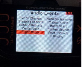
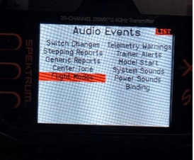
1. Navigate to the AUDIO EVENTS on the main Function List and click it. This will take you
to the Audio Event screen as shown in Figure 21. Audio Events screen.
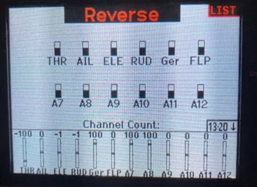
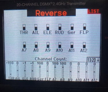
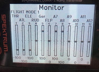
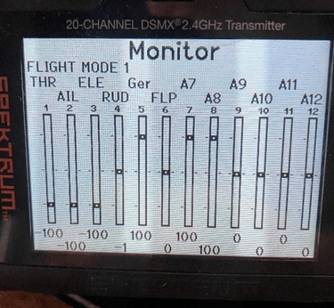
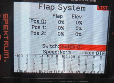
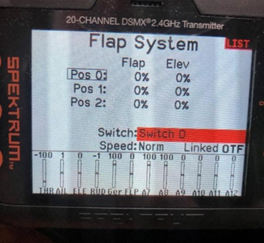
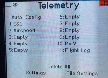
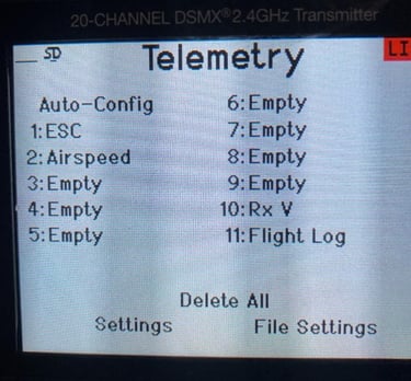
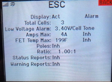
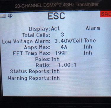
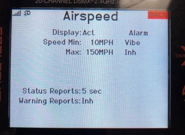
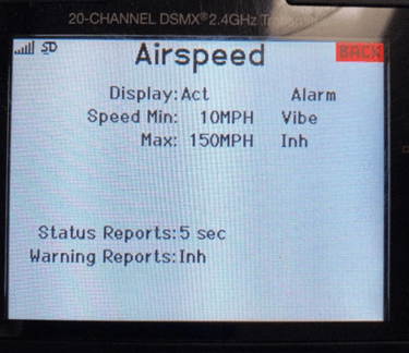
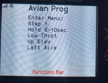
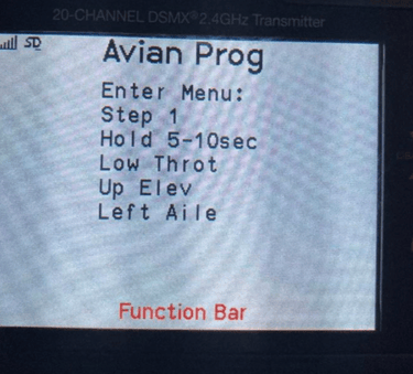
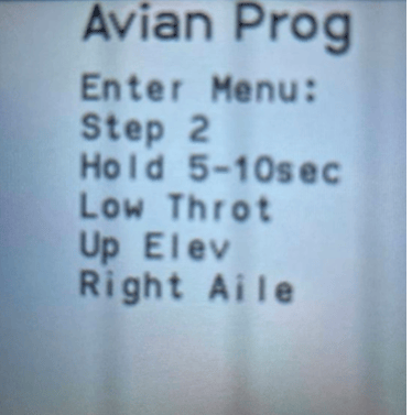
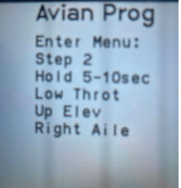
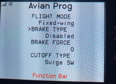
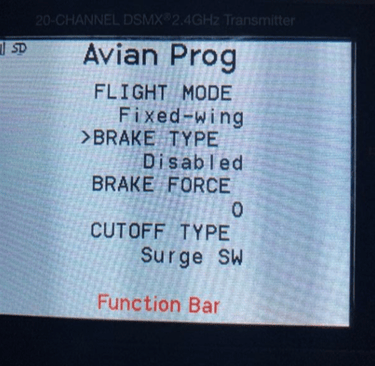
Figure 21.0 Audio Events screen
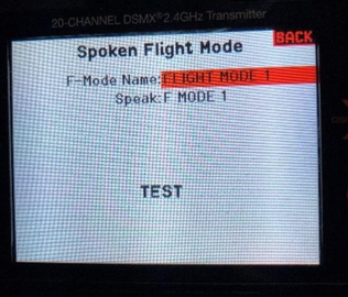
Highlight Flight Modes and click it. Figure 22.0 shows the screen labelled Spoken Flight Mode before we customize it.
Figure 22.0 Spoken Flight Mode Screen before customizing
2. If you make selections on Switch B you will see the text change indicating the mode you have selected. Go to first position (position 0) on Switch B and highlight the F-mode Name, it should show FLIGHT MODE 1. Click on it and it will take you to the Edit Flight Mode Name screen. Scroll and select the existing name. Using the editor change this name to Normal Mode. When done, use the BACK button to get back to the Spoken Flight Mode screen and scroll to highlight the Speak parameter. Click it and scroll through the spoken phrases until you find Normal Mode and click it. Use the TEST parameter to hear the spoken phrase. You may need to turn up the audio to hear it.
3. Change Switch B for the middle position (position 1), which is Flight Mode 2 . Go through and edit this to read AS3X MODE. Scroll through the audio phrases until you find Stabilization Mode and click that. Test for the audio verification. I think the voice will say Stability Mode even though the text says Stabilization Mode, a little mismatch by Spektrum there.
4. Position Switch B for position 2, Flight Mode 3 and edit this name to SAFE Mode as you did for Modes 1 and 2. Find the spoken phrase Safe Mode and click on that. Then back out to save all of this and that’s it. We have not yet actually programmed what happens with these switch selections, we just defined what the screen shows, and voice message is for these 3 positions. Next, we will program the specific operational modes these different flight mode selections will enable.
Final note on this, even though the Function List refers to this as the Audio Event function, it allows us to edit the text for modes as well. Now when you change the position of Switch B you will see the selected flight mode change on the main screen and you will hear the selected mode spoken once, according to the selection that is made.
2.12 Programming for Switch Selectable Normal, AS3X and SAFE flight modes.
Preface:
In the last programming section, we programmed what flight modes we want the Switch B positions to select. There are three modes, Normal, AS3X and SAFE to choose from. I use the forward position of Switch B for the Normal Mode, the middle position for AS3X and the last position for SAFE. You can change that to suit your preferences. For a quick review:
Flight mode 1. Normal Mode: in this mode there are no gyro assisting in the flight controls.
Flight mode 2. AS3X Mode; in this mode the gyro helps stabilize against rapid changes in attitude due to wind gusts or anything that would throw the plane off line. If the model tends to wobble on some axis, the gains in this mode need to be reduced. But it’s a trial-and-error test since every plane has its own unique aerodynamics.
Flight mode 3. SAFE; in this mode we have full scale, automatic flight leveling. Letting go of both control sticks will allow the gyro to bring the plane to straight and level flight. The pilot will still be able to move the flight controls, but with slightly reduced rates, i.e. not as much deflection as you get in AS3X or Normal modes.
Programming Steps:
1. Navigate to the Forward Programming option under the Function List and click it. Figure 23.0 shows what this new screen looks like.
Figure 23.0 Forward Programming Main Menu
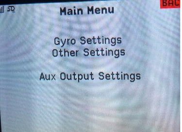
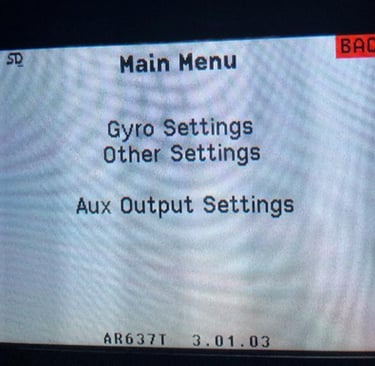
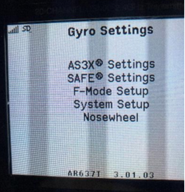
2. Highlight Gyro Settings and click it. Figure 24.0 shows this new screen.
Figure 24.0 Gyro Settings
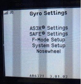
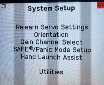
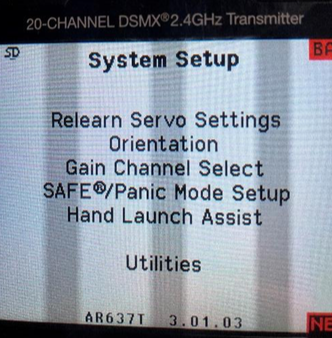
3. Highlight the option System Setup and click it, Figure 25.0 shows the next screen.
Figure 25.0 System Setup under Forward Programming
4. The first selection the list is Relearn Servo Settings. Highlight this parameter and click it. That’s all you must do for this step. In a few seconds it will be done and you’ll need to select “Apply” and “Complete” to finish this step. You will end up back on the Main Menu, Gyro Settings screen. As I mentioned previously, this is a very import step. It tells the program to read and learn the latest selection of directions to move the servos to achieve the desired results. It would seem reasonable to expect that part of this calibration would be done automatically, but it’s not. You must do this step manually, otherwise you risk having the SAFE mode fly your plane into the ground before you can figure out what is going on.
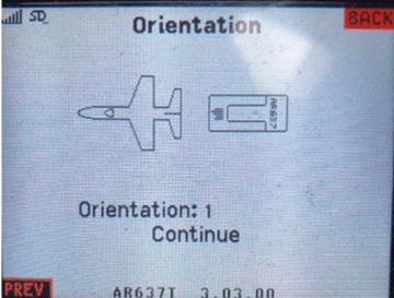
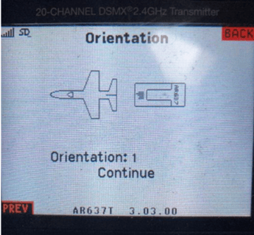
5. Navigate back to the Main Menu and click on Gyro Settings followed by System Setup. again. The second option below Relearn Servo Settings is Orientation, select and click it. Follow the prompts that will take you through the gyro calibration process. It’s straightforward. At the end it shows you how the receiver should be physically oriented in the model. Verify that your actual receiver orientation agrees with the depiction on the screen. Highlight Continue and click it. Figure 26.0 shows a typical receiver orientation that should agree with how it’s physically mounted in the model. From this point on you cannot move or reposition the receiver without re-running this calibration sequence we just completed. If you need to relocate or re-orient the receiver you must go back and perform this step again.
Figure 26.0 Results of performing the receiver orientation calibration.
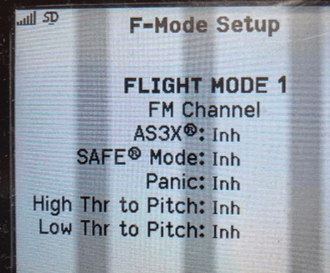
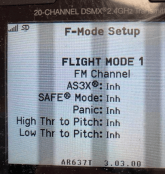
Navigate back to the Gyro Settings screen, highlight F-Mode Setup and click it. Here’s where we assign the actions the receiver will take for each switch B position. Position the Switch B to forward most (furthest away from you), this should show on the screen as Flight Mode 1. I know we renamed it Normal Mode earlier, but this program will not use our new name, NORMAL, during this phase of programming. This new mode name only appears on the Main Screen. Figure 27.0 shows the F-Mode Setup screen. Under Flight Mode 1 you’ll see a list of options. In this mode we do not want AS3X or SAFE to be active so all the available options should show Inh. This is for flying without any gyro support
Figure 27.0 Flight Mode 1 (NORMAL) Options
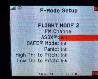
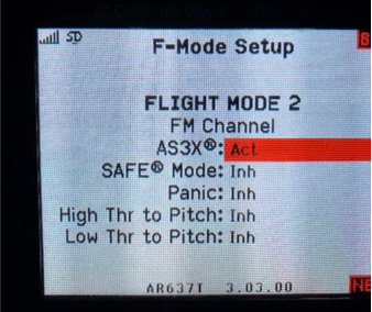
6. Select the middle position for Switch B (position 1). This is Flight Mode 2. In this position we want the AS3X function to be active by itself, no SAFE. Scroll to the AS3X option and click it. Scroll to change assigned action to say “Act”, or active. On the next line, SAFE Mode, scroll to select Inh. Now when we select this position on Switch B, we will have the AS3X mode active by itself, without SAFE. Figure 28.0 shows Flight Mode 2 (AS3X) mode selection.
Figure 28.0 Flight Mode 2 selections
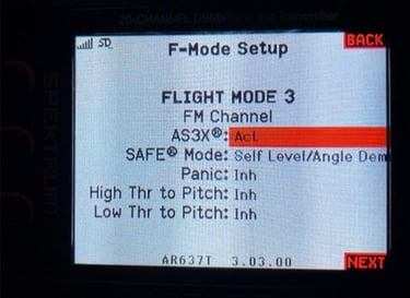
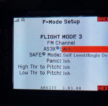
7. Select Switch B to position 2 (closest to you). The screen should show you’re on Flight Mode 3. We will program both the AS3X and SAFE modes to be active. Figure 29.0 shows the screen for Flight Mode 3 (SAFE). Scroll to the AS3X option and set it for Act and do the same for the SAFE Mode. Now you’ll have both modes i.e., AS3X and SAFE engaged when you make this switch selection.
Figure 29.0 Flight Mode 3 AS3X and SAFE
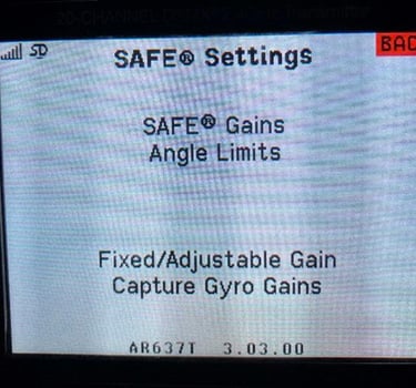
8. Gains and Angle limits for SAFE mode
In this section we can change the gains and angle limits for the safe mode from the factory settings. For the gain settings, I leave the factory values as is unless there is a reason to change them. For example, if I’m encountering unstable flight performance when in either the AS3X or SAFE modes, like an oscillating roll for example, then it’s time to reduce these gain values. You’ll need to experiment a bit to determine which gains the AS3X or the SAFE gain values reduce the oscillations.
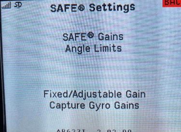
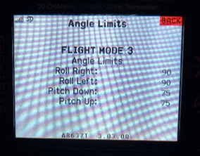
Navigate to the Gyro Settings screen and select SAFE Settings and click it. Figure 30.0 shows the SAFE Settings screen. Highlight Angle Limits and click it. Figure 30.0 shows the Angle Limits screen. For the Angle Limits, I set them for maximum which is +,-90 deg roll and +,-75 deg pitch. Highlight these limits for Roll Right, Roll Left, Pitch Down and Pitch Up and set them to 90 and 75 respectively. Figure 31.0 shows this screen. These maximum limits allow for enough authority to perform reasonably tight turns and climbs while the SAFE mode is active. SAFE won’t let you make aileron rolls or loops but with these limits it does allow for good maneuverability. For aerobatic maneuvers you will need to select the NORMAL or AS3X mode. The SAFE mode will restrict and counter your control inputs. Remember it acts as a smart stabilization, always striving to self-level, but yielding for turns and nominal climbs/dives. For example, if you lose orientation of the airplane, letting go of the control sticks causes the aircraft to automatically return to level flight.
Figure 30.0 SAFE Settings screen
Figure 31.0 Angle Limits settings
10. Bench Testing AS3X and SAFE modes.
This final step is for testing the flight modes prior to taking flight.
1. Before we begin have the battery unplugged. Then plug the battery in to make sure the system reboots. The first sign to look for is for the servos to twitch twice indicating the AS3X and SAFE modes are available. Go to the Normal mode and check for correct control surface movements. Also check for neutral surface positions with hands off both control sticks. You must be in Normal mode to check for neutral controls. If you’re in SAFE mode, the controls could be deflected to compensate for the model not sitting perfectly level. If your model is a taildragger sitting on a flat surface, the elevators will be deflected down with the sticks in neutral position to compensate for the slightly nose-up attitude. For a nosewheel plane this isn’t an issue.
2. To test the AS3X mode the throttle needs to be advanced beyond 25%. If you haveAS3X+ this is no longer a requirement. For testing AS3X hold the model firmly and roll the model quickly in one direction and then in the opposite. Similarly to you taking the control stick and trying to waggle your wings. You should hear the aileron servos reacting to correct for this high rate of roll. The control will only respond while the plane is rolling. Once the plane stops rolling at any angle, the servos will stop reacting. Testing requires you listen for servo movement as you are rolling the plane. Do the same of the pitch and yaw channels.
3. For testing the SAFE mode, use Switch B to select SAFE. Then roll the plane to one side, say to the right about 45 degrees and hold the angle. Note the ailerons responding to this movement by deflecting the ailerons so that it will bank the plane back to the left and it will hold this correction until you manually bring the plane back to level while the ailerons move back to neutral. Perform this test in the other direction and verify it responds correctly. If you are not sure of the corresponding reactions of the control surfaces in SAFE mode, please consult with someone to verify the controls are moving properly.
Do the same test for the elevators.
2.12 Installing the propeller.
With the battery unplugged, install the propeller. Make sure the throttle is all the way back and the cut switch is in the cut position. Plug in the battery, stay clear of the prop and keep others away and prepare to test the motor and reverse thrust ac on. This test should be done on the taxiway or runway, not in the pits.
Put Switch C in the FWD position, (full forward) and flip switch G (or whatever switch you programmed for Throttle cut) and ramp up the rpm to 10-20%. Verify the air ow is going towards the tail. Pull the throttle back all the way, flip switch C to the reverse position (full back) and ramp up the rpm verifying the air ow is going out in the forward direction.
You might nfid as I have on some ESCs that the first me a er power up, the motor runs in reverse, even when Switch C is in the forward position. If this is happening, cycle Switch C and see if it works properly.
2.13 Final Notes.
There is more than one way to program the receiver to achieve the same results as outlined in these procedures. But this seems to work fine, and it provides me with a consistent method to get the results I need. Now get out there and have fun with this hobby!
Using A Spektrum Transmitter/Receiver.